
7 tips for optimizing your 3D cell imaging and analysis workflow
As the field of cell biology moves toward increasing complexity of assays, 3D cell systems have proven to provide more physiologically relevant information as compared to traditional 2D assays for drug discovery and disease modeling. In traditional 2D systems, cells stretch, adhere, and grow on a flat surface; whereas 3D systems better mimic the in vivo tissue environment through cell-cell/ECM interactions, compound penetration, and dose response.
With increased complexity of 3D assays comes new challenges related to cellular imaging such as longer image acquisition and analysis times, as well as increased data storage requirements. By using the right tools and techniques, you can overcome these challenges and obtain reliable data in a more efficient manner.
Here are seven tips for optimizing your 3D cell imaging and analysis workflow.
1. Use the proper instrumentation and technology for imaging 3D cell cultures
When working with 3D cell cultures, it is not sufficient to acquire an image of one cell plane, like in traditional 2D cell cultures. Instead you need to take a range of images in vertical planes (typically 10-15 images), referred to as a z-stack. Automated confocal imaging platforms, such as the ImageXpress® Micro Confocal High-Content Imaging System, enable you to image a thinner optical section of the 3D structure and significantly reduce background haze, resulting in better image resolution and finer cellular detail. The ImageXpress system’s water immersion objectives also play a key role in enhancing image quality.

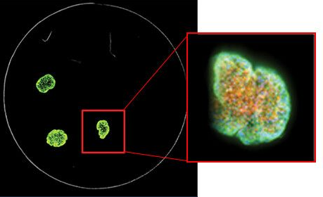
A stack of confocal images was acquired in the z-plane spanning roughly half the depth of the spheroid (left). Only some cells of the spheroid are in focus at any given plane, so for ease of analysis, the images were collapsed into a single 2D image to combine the in-focus areas (right).
2. Use microplates that are designed specifically for 3D imaging
It is important to use microplates designed specifically for 3D imaging. Usually these are 96- or 384- well clear bottom plates. The round U-bottom plates from Corning are convenient for making spheroids and also ideal for 3D imaging. These plates allow you to keep the spheroid centered and in place during image acquisition. Flat bottom plates on the other hand tend to be problematic, as they make it difficult to keep the sample centered.
3. Follow proper cell preparation techniques prior to imaging
It is important to consider the type of 3D sample that you are using, as different samples have different preparation and imaging requirements. When dealing with solid objects, such as spheroids or thick tissue samples, there is a limited distance that you can visualize due to limited light penetration and light scattering which causes interference of cells. Alternatively, cells in matrices such as Matrigel are transparent, allowing you to visualize the object and perform analysis with greater light penetration.
The staining of 3D cellular objects such as spheroids can be tricky, since dyes have to penetrate not only the surface but also the interior of the sample. In the case of Hoechst dye, which is used for nuclear staining, you may need to use 2X-3X greater concentration in order to get effective penetration. In turn, you may need to allow a longer duration for staining. Typically a dye such as Hoechst requires 15-20 minutes for staining. However, when dealing with spheroids, you may need to allow 2-3 hours for staining. Some dyes are lipophilic and may become stuck on the surface instead of penetrating the sample. Staining with antibodies is especially challenging and scientists are still working to develop effective staining protocols.
4. Locate the center position of your 3D sample at the start of image acquisition
To start the imaging process, you first need to find the position of the object at the center of the imaging site and find the first focus that would approximately be in the middle of the z-position (vertical position). As an example, if you are imaging a spheroid which is approximately 500 microns in diameter, the starting position would be approximately 50 microns above the well bottom. At this starting position, you can then adjust your exposure and offsets for different channels.
Sometimes the spheroids become off center, so you may need to adjust the plate dimensions to make sure that the spheroids are centered. You might also check across the plate at different corners to make sure that the spheroids are in view.
5. Define the range of your 3D image acquisition, from start to finish
This involves acquiring a stack of images at different depths within the object and defining exactly where you need to start, where you need to end, and also defining the number of steps in between. Typically for a 10X objective, you may start with an 8-10 µm distance between steps. For a 20X objective, you would start with a 3-5 µm distance between steps, and so forth.
Although increasing the number of steps improves quality of the analysis and visualization, an excessive number of images can prolong your acquisition and analysis time and overload data storage. Plus, taking too many images could cause your sample to fade. Ultimately, it’s a matter of experimenting to find the right balance. Typically I use two different protocols for a single plate. One uses a greater distance between slices and the other uses less.
It is also very important to specify the type of projection image that you want to take at the start of acquisition. Typically for confocal imaging, the object is set at “maximum projection image,” which automatically generates a lot of information regarding the sample. At this point, you can choose to analyze only the projection image in lieu of 3D analysis to speed up the process.
6. Utilize QuickID and water immersion objectives to help reduce your image acquisition time
During acquisition, 3D objects may drift away from the center of the well, making them difficult to find. This is especially true if you are dealing with spheroids in flat bottom plates. To overcome this challenge, our ImageXpress system includes a feature called QuickID targeted image acquisition. The system images at low magnification to find the object of interest, then automatically acquires the object of interest in a single field of view at higher magnification. This significantly reduces acquisition time and data storage requirements. The use of water immersion objectives is also beneficial, as they collect higher signal from the 3D sample, thus enabling you to decrease your exposure time and increase the speed of acquisition.

7. Use the appropriate 3D analysis software
Our cellular imaging systems include MetaXpress® High-Content Image Acquisition and Analysis Software, which provides many tools to make analysis a more seamless process. The easiest approach would be to combine the in-focus areas for your stack of images into a single 2D projection using the software’s Maximum Projection algorithm. You can use tools for normal 2D analysis such as count nuclei, cell scoring, and neurite outgrowth.

For 3D analysis, you can find objects of interest in each z-stack and then combine them. For example, if you are working with spheroids or cells in Matrigel, the “Find round object” tool enables you to find the object in a single step once you define approximate object size and threshold of intensity. Another common tool is “Connect by best match.” Here, you select your analysis protocol (e.g., count nuclei, live/dead, or cell scoring) and run it separately for each z-slice. The algorithm then connects certain objects between adjacent z-slices in a 3D volume based on the maximum shift of objects between slices that you designate as acceptable. You can then visualize your objects in a 3D format and more importantly, you can perform a 3D volumetric analysis to identify volume, distance between objects, etc.
To learn more about optimizing your 3D cell imaging and analysis workflow, explore our 3D Cell Models web page.